

When an OEM engineer specifies an electric transaxle for a tow tractor, an AGV, a floor scrubber, or a golf cart, most of the conversation tends to orbit rated torque, top speed, and gear ratio. Braking, by contrast, is treated as a checkbox. That habit is expensive. Across utility vehicles and automated guided carts, a meaningful share of safety incidents and warranty claims trace back not to the motor but to a brake that was undersized, wired to the wrong supply, or never validated against the actual ramp angle the machine climbs every shift. This guide walks procurement and design teams through a repeatable way to specify, verify, and accept electromagnetic brakes on electric transaxles before a purchase order is released.
The good news is that the physics are simple and the component is mature. The risk is that “simple” becomes “assumed,” and assumptions about holding torque or release voltage quietly propagate from a sales datasheet into a fleet of 200 machines. Below is the checklist we recommend B2B buyers use when sourcing electric transaxles for people-carrying or load-carrying vehicles.
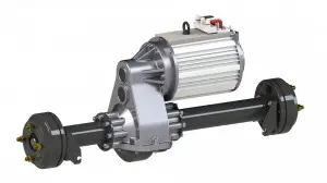
How an Electromagnetic Brake Works Inside a Transaxle
An electromagnetic brake used on an electric transaxle is almost always a spring-applied, electrically released design. In its resting state the spring presses a friction disc against the rotor, locking the output shaft. When the controller energizes the coil, the magnetic field pulls the armature plate back against the spring, releasing the disc and freeing the shaft to rotate. The critical implication for safety is the direction of failure: loss of power means the brake engages, not disengages. That fail-safe characteristic is precisely why this architecture dominates people-carrying and load-carrying vehicles.
On an integrated transaxle, the brake typically sits at the motor end or directly on the output shaft, depending on whether the supplier uses a motor-mounted or axle-mounted configuration. The placement changes how heat is managed and how service is performed, both of which matter for total cost of ownership over a multi-year deployment. For procurement, the placement also affects spare-part strategy, because a motor-mounted brake is often serviced as part of the motor, while an axle-mounted unit may be replaced independently.
Deriving Holding Torque Instead of Copying a Datasheet
The single most common procurement error is selecting a brake by peak motor torque. Holding torque and motor torque are different quantities. Holding torque must resist the gravitational component of the machine’s mass along the slope, plus a margin for wind, load shift, and friction-disc wear. A practical engineering rule is to size for at least 1.5 to 2.0 times the static holding requirement at the steepest grade the vehicle is certified to park on, and to re-check that margin at the disc’s end-of-life friction coefficient rather than its fresh value.
Calculating holding torque from ramp angle
For a machine of mass m on a slope of angle θ, the gravitational force along the slope is m × g × sin(θ). Converted to a torque at the wheel radius r, you get T = m × g × sin(θ) × r. As a working example, a 1,200 kg tow tractor parked on a 15° ramp (about 27% grade) with a 0.20 m effective wheel radius needs roughly 1,200 × 9.81 × 0.259 × 0.20 ≈ 610 N·m of holding torque at the wheel. After accounting for the transaxle reduction ratio—say 16:1—the brake at the motor side must hold about 38 N·m. Add the 1.5–2.0 safety factor and you are shopping for a minimum 60 N·m holding brake, not the 30 N·m unit that a low-cost quote might include.
This is where B2B buyers lose leverage if they only compare unit price. Two quotes labeled “48V, 40 N·m” can behave completely differently once real grade, payload, and degradation are modeled. Insist that the supplier state holding torque at the brake, not at the wheel, and confirm the test method and the temperature at which it was measured. A brake rated at 25°C may deliver noticeably less at 60°C in a sealed axle.
Tip: Always request the brake’s holding torque measured at the end of a 1,000-cycle burn-in, not the fresh-unit value, because friction coefficient drops as the disc seasons.
Matching Brake Voltage to Your Battery Pack
Electromagnetic brakes are commonly offered in 12V, 24V, 48V, and 72V coil versions, with 24V and 48V the most frequent on industrial electric vehicles. The brake coil must match the available control supply, not the traction pack. A frequent failure mode is specifying a 48V brake while the machine only carries a 24V auxiliary rail, or vice versa, leaving the brake partially released under load. For mixed fleets, standardize on one brake voltage to simplify spares and reduce assembly errors.
Pay attention to inrush and holding current. A typical 48V, 40 N·m brake may draw 0.6–0.9 A holding current and briefly more during engagement. Over a long parked shift this is negligible, but it matters for the auxiliary supply sizing and for any fail-safe release interlock logic that must guarantee release before motor drive. Document the minimum release voltage in the specification—for a 24V coil this is commonly 18V, and for a 48V coil around 36V—so the acceptance test has a pass criterion.
Response Time and Engagement Consistency
Engagement time—the delay between de-energizing the coil and full lock—typically ranges from 15 ms to 60 ms for industrial brakes of this class. For AGV applications where the vehicle must hold position the instant the controller cuts power, spec the upper bound tightly and validate it on the bench. Inconsistent engagement, where one unit locks in 20 ms and another in 55 ms, is a leading cause of position drift on inclined conveyor transfers and of load shift during automated pick-and-place cycles.
Ask the supplier for the spread across a production lot, not just the nominal value. A credible vendor will quote engagement time as a range with a documented test current and temperature, and will explain how the value changes as the friction disc wears. If the vendor can only give a single number with no lot data, treat that as a gap in the quality file.
Spring-Applied, Electrically Released: Why It Matters for Your Risk File
The fail-safe nature of a spring-applied brake should be documented in your functional safety or risk assessment file. If the machine carries personnel or operates near workers, the brake’s loss-of-power engagement is a protective function, not an optional feature. Procurement should capture the supplier’s declaration that the brake is spring-applied and confirm there is no scenario—low voltage, controller fault, connector loss—where the brake releases unintentionally. This is a clause worth adding to the procurement specification even if it feels obvious, because it converts an assumption into a contractual commitment.
For machines sold into regulated environments, keep the supplier’s declaration alongside your own verification records. Auditors reviewing a safety case will ask for both the component-level fail-safe statement and your evidence that the delivered units match it, which is why serialized or lot-level test data matters.
Duty Cycle, Thermal Limits, and Where Brakes Fail in the Field
Brakes on transaxles are designed primarily for holding and occasional stopping, not for continuous friction service like a service brake on a passenger car. Repeated dynamic stops heat the disc, and sustained heat reduces holding capacity. Typical industrial electromagnetic brakes are rated for intermittent duty, often in the ED (duty factor) range of 10%–40%, with continuous holding at rated torque permitted because no relative motion occurs. Field failures cluster around two patterns: using the brake as the primary deceleration device on a downhill route, and parking a hot brake on a grade immediately after a long descent.
For steep, repeated descents, specify a transaxle with regenerative braking or a separate mechanical service brake for dynamic stops, and reserve the electromagnetic unit for parking and hold. This split protects the brake and extends its service interval beyond the typical 1,000–3,000-hour range seen in light-duty service. For heavy tow tractors that descend loaded ramps all day, expect to shorten the inspection interval and budget for disc replacement accordingly.
Batch Acceptance: Sampling and Verifying Brakes at Incoming Inspection
Once the specification is fixed, the next failure point is incoming quality. A transaxle arrives as a sealed assembly, and the brake inside is invisible until it fails. B2B buyers should negotiate an incoming inspection and functional test protocol with the supplier rather than trusting a certificate of conformity alone. At minimum, sample for holding torque, release voltage window, and engagement time, and record the results against the lot number.
A practical AQL plan for brake verification
For production lots of 50–300 transaxles, a common plan is ANSI/ASQ Z1.4 general inspection level II, AQL 1.0 for critical brake-function defects, which maps to sample sizes of 8–20 units depending on lot size. At least one unit per lot should be fully torn down for a brake-function bench test: measure holding torque under rated current, confirm release at the low end of the supply tolerance (for example, a 24V brake releasing at 18V minimum), and record engagement time. Keep the tear-down unit as a reference standard. For high-volume programs, move toward 100% end-of-line brake torque testing at the supplier with serialized brake test data you can audit by serial number on demand.
Document the acceptance criteria in the purchase order. Vague language like “brake works” is not enforceable; “holding torque ≥ 60 N·m at 24V after 1,000 cycles, engagement ≤ 50 ms” is. The purchase-order specification is your only leverage if a lot drifts, and it is what your incoming inspection team will measure against.
Common Procurement Mistakes to Avoid
- Selecting brake size from motor torque instead of derived holding torque at the certified grade.
- Matching the brake coil to the traction pack voltage rather than the auxiliary control supply.
- Accepting a fresh-unit holding torque number without a burn-in or end-of-life value.
- Treating the electromagnetic brake as the sole dynamic braking device on steep routes.
- Omitting engagement-time spread and release-voltage window from the acceptance criteria.
- Buying the lowest quote without confirming the supplier can provide serialized brake test data.
- Skipping the spring-applied fail-safe declaration in the risk assessment file.
Each of these is a small omission on paper and a large liability in the field. The cost difference between a correctly specified brake and an undersized one is usually only a few percent of the transaxle price, but the downstream cost of a field recall, a damaged load, or an injured operator is not. Procurement teams that treat braking as a first-class specification line, rather than a checkbox, protect both the program budget and the end user.
FAQ
Can an electromagnetic brake hold a vehicle on a slope indefinitely?
Yes. For parking and holding, the brake is designed for continuous static service because there is no relative motion and therefore negligible heat generation. The limiting factor is the holding torque margin versus the gravitational load, not time. For a 1,200 kg machine on a 15° grade, confirm the brake holds at least 1.5× the computed requirement and document it in the vehicle’s certification file so the assumption is auditable later.
What happens if the brake coil loses power while driving?
In a correctly wired spring-applied brake, loss of coil power engages the brake and locks the shaft. That is the intended fail-safe behavior. The risk is an unintended release caused by a faulty interlock that cuts power to the brake while the motor is still driven; your controller logic must guarantee the brake is released only when the drive is active, and re-engages on any fault or stop command. Validate this sequence on the bench, not just on paper.
How do I choose between a 24V and 48V brake?
Match the brake coil to the control supply your machine actually provides, independent of the traction voltage. If you run a 48V auxiliary rail, choose a 48V coil; if only 24V is available, choose 24V. Standardizing one voltage across a fleet simplifies spares and reduces wiring errors during assembly, which is why many OEMs fix a single brake voltage across their entire product range.
Is engagement time important for AGVs?
It is critical. AGVs that transfer loads on inclined sections or at conveyor interfaces must hold position the moment power is cut. Specify an upper bound on engagement time—commonly 15–60 ms for this class—and verify the lot spread, because a unit that drifts to 55 ms can cause position error and load shift on repeated cycles. Tight engagement consistency is often more valuable than a slightly faster nominal time.
Should I rely on the brake for downhill deceleration?
No. Use regenerative braking or a dedicated service brake for dynamic stops, and reserve the electromagnetic brake for parking and hold. Repeated friction stops raise disc temperature and degrade holding capacity, shortening service life well below the 1,000–3,000-hour light-duty range. A split braking architecture is the standard recommendation for any vehicle with frequent steep descents.
What test data should the supplier provide with each lot?
Request holding torque at rated and end-of-life conditions, release-voltage window, engagement time, and for high-volume programs serialized end-of-line brake torque records. Pair this with your own AQL incoming inspection so a drifting lot is caught before it reaches the assembly line. Keep the records linked to lot and serial numbers so any future field issue can be traced back to its production batch.
Related Pages
- Electric Transaxle Technical Specifications Guide
- What Voltage Electric Transaxle Should You Choose
- Electric Transaxle vs Gearbox
- How to Match Electric Transaxle with Motor
Post time: Sep-18-2026